How to Install LED Lights on an RC Car or Crawler
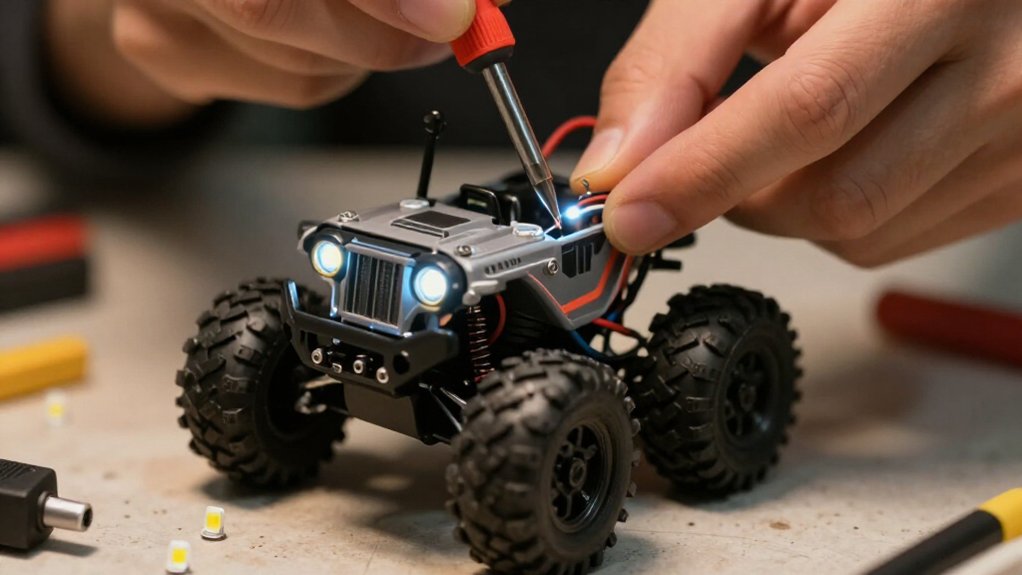
Choose a model-specific LED kit when available, and confirm it fits your RC car or crawler. Disconnect the battery, remove the shell, then test-fit brackets before marking holes.
Cut small openings with a Lexan-safe tool, smooth the edges, and seal them with flexible adhesive. After curing, mount the LEDs and connect the harness to an approved receiver port.
Keep connectors outside the receiver box, check polarity, and route wires clear of moving parts. Check clearance through full suspension travel; more tips follow.
Choose LED Kit Type
Choose an LED kit that matches your vehicle and the functions you want. When available, select a model-specific kit; it typically supplies compatible parts and installation instructions. A complete vehicle package may include front and rear LED bumpers, a power harness, instructions, and required hardware.
Check the fitment listing before you commit, especially if you run upgraded components. The listed Traxxas kits won’t work with vehicles fitted with the Magnum 272R transmission.
If no model-specific option fits, choose a universal kit based on how you want the lights to operate. Basic systems illuminate when you power the vehicle; other kits use a switch or radio control. Choose an advanced kit with a controller if you want simulated brake lights and turn signals for your vehicle.
Gather Tools and Materials
Before you start, check that your LED kit includes the correct front and rear supports or bumpers, power harness, instructions, and hardware.
Match the kit to your RC model, or choose a universal set with the lighting functions you want. Lay out these items before installation:
- Choose a model-specific kit or a universal kit that provides your desired lighting functions.
- Use a 2 mm hex driver to open the receiver box; add the tools your model needs for bumper removal.
- For custom bodies, ready a Lexan-compatible cutter or drill bit sized for each LED support.
- Set out adhesive tape or glue to secure LEDs, brackets, and wiring wherever the instructions specify.
- Keep the kit instructions and required hardware beside your tools, within easy reach.
Step 1: Remove the RC Body Shell
Start by switching off the RC vehicle and disconnecting or removing its battery. Keep power isolated while you handle the shell; don’t rely on the switch alone. Locate each body post, then remove its retaining clip or unscrew its fastener, depending on your model. Set clips and screws aside in a parts tray so you can reinstall them without losing hardware.
Once all posts are free, grasp the shell at sturdy edges and lift it slowly, without twisting. Watch the antenna and any wiring attached to the body as you raise the shell; guide them clear rather than pulling. If a wire catches, pause and free it before continuing. Place the removed shell on a clean, stable surface, with its exterior protected from scratches.
Step 2: Test-Fit LED Brackets
With the shell removed, position each LED bracket, or light bucket, over its intended opening and check that it sits securely and points the beam where you want it. Keep each bracket against the body without forcing it; a twisted or rocking fit can shift the beam and strain the mount. Check alignment, confirming the lens or LED will sit centered in the opening. Test every bracket before applying adhesive or installing screws.
Make sure supports contact the body evenly and that wiring, body posts, suspension parts, and other components remain clear. Adjust bracket orientation as needed, then repeat the check with the full set in place. Don’t commit a bracket until it stays put and maintains the intended beam direction during final placement.
Step 3: Drill LED Mounting Holes
Drill LED mounting holes only after each bracket sits in its intended position. Mark bodywork at each light bucket, using the test-fitted bracket as your reference. Confirm the marks align with the support openings and that no hole will interfere with nearby body features.
Use a Lexan-cutting tool rather than a standard twist bit, which can grab and crack flexible shell material. Cut a small pilot opening at each mark, keeping the tool square to the panel. Make every opening slightly smaller than its support; don’t remove material to the final size in one pass.
Enlarge each hole gradually, then test-fit its support after each adjustment. Stop when the support seats securely with minimal play. Before installing brackets, verify each opening’s position.
Step 4: Snap LEDS Into Bezels
Once the mounting holes fit their supports, press each LED into its matching bezel or light bucket until it’s held securely.
Check that the LED sits firmly in the bracket and that the bezel faces outward through the body opening. You should feel the assembly seat without needing excessive pressure. A snug fit keeps the light from shifting during handling and limits stress on the bodywork. If the LED feels loose, inspect the fit before adding hardware or adhesive.
Use the kit’s retaining screw when the bezel provides one; tighten it only enough to hold the LED in place. If your kit calls for adhesive instead, apply a small point of glue at the specified contact area and let it set before handling.
Step 5: Aim Beams for Visibility
Aim the front LEDs slightly downward to light the ground ahead without shining into other drivers’ eyes, and point the rear LEDs outward and backward so they’re visible from behind.
Check each LED sits securely in its light bucket; the bucket helps shape and direct the beam. With the vehicle on, test the lights on a driving surface. Observe where each beam lands, then adjust the LED angle until the trail is clearly lit without glare.
Make changes and retest, since a slight shift can move the brightest area or leave a dark patch. After you secure the wiring and reinstall the bumpers, recheck alignment; tightening parts can shift a light or its bucket. Confirm the rear beams remain visible from behind at ride height.
Step 6: Connect the Controller and Receiver
With the beams aligned, connect the LED power harness to the receiver. Open the receiver box with a 2 mm hex wrench or driver. Remove the clamp and lid screws, then lift the lid.
Feed the harness through the lid opening. Plug its black connector into an unused CH1 port or the CH3 port on a 3- or 5-channel TSM receiver. Don’t use the V/T or RPM slots; they aren’t suitable for the LED harness.
Keep the harness’s red connectors outside the receiver box. Before closing it, route every wire clear of the lid seam to prevent pinching. Check that the blue O-ring sits correctly in its groove, then confirm the harness and connectors are secure. Refit the lid and clamp, tightening the screws evenly.
Verify Lights Through Suspension Travel
Slowly compress and extend the suspension to check that the LED wires have enough slack throughout its full travel. Watch wiring near the shock towers, chassis, and bumpers as you cycle the suspension; these areas can pull or pinch cables. Keep each run clear of shocks, wheels, and other moving parts, checking both compression and extension. If a cable turns taut or catches, reroute it before further testing.
Secure the revised route with adhesive tape, but leave enough slack for full movement without letting the wire dangle into a wheel. Cycle the suspension again, then switch on the lights and inspect every connection. Confirm connectors remain seated and all LEDs still work. Repeat the check after securing any additional wiring or changing its route.
LED Wiring Polarity Mistakes
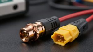
Before powering up, plug the harness’s black connector into a free receiver channel, such as CH1 or CH3, not the TSM receiver’s V/T or RPM slot. Keep red harness connectors outside the receiver box while routing the black plug inside. Either red male plug fits either female plug; don’t treat them as front- or rear-specific. Seat every connector fully, and inspect wires for pinching or damage.
| Check | Correct action | Mistake |
|---|---|---|
| Receiver plug | Use free CH1/CH3 | V/T or RPM |
| Red plugs | Match either pair | Assume front/rear |
| Routing | Keep red plugs outside | Trap in box |
| No lights | Recheck orientation | Leave loose |
Connect battery and switch on. If LEDs stay dark, recheck plug orientation and connections; don’t force a reversed or misaligned plug before your next power-up.
Seal Drilled Body Edges
After drilling the LED mounting holes, smooth each rough edge so it won’t catch or split the Lexan. Use a fine sanding stick or a piece of fine-grit sandpaper to remove burrs without enlarging the hole. Work around the circumference, then wipe away plastic dust. Apply a thin bead of Lexan-safe flexible adhesive or clear silicone around the exposed edge of each hole. Don’t let sealant reach the LED lens or the surface where its support seats. Material in either area can dim the light or prevent a secure fit. Leave the body undisturbed and let the sealant cure completely according to the product instructions. Fit the LED supports only after curing, so handling won’t smear the seal or loosen its bond.
Conclusion
You’ve mounted the LEDs, routed the wiring, and checked clearance through suspension travel. Before your next run, confirm each light works, secure loose leads, and seal the drilled body edges to limit cracking and moisture entry. If a light stays off, recheck polarity and connections before powering up again. Keep the wiring clear of moving parts, then reinstall the shell and test the crawler at low speed. A careful final check helps protect your installation on the trail.