XT60 vs EC5 Connector: Which Handles More Current?
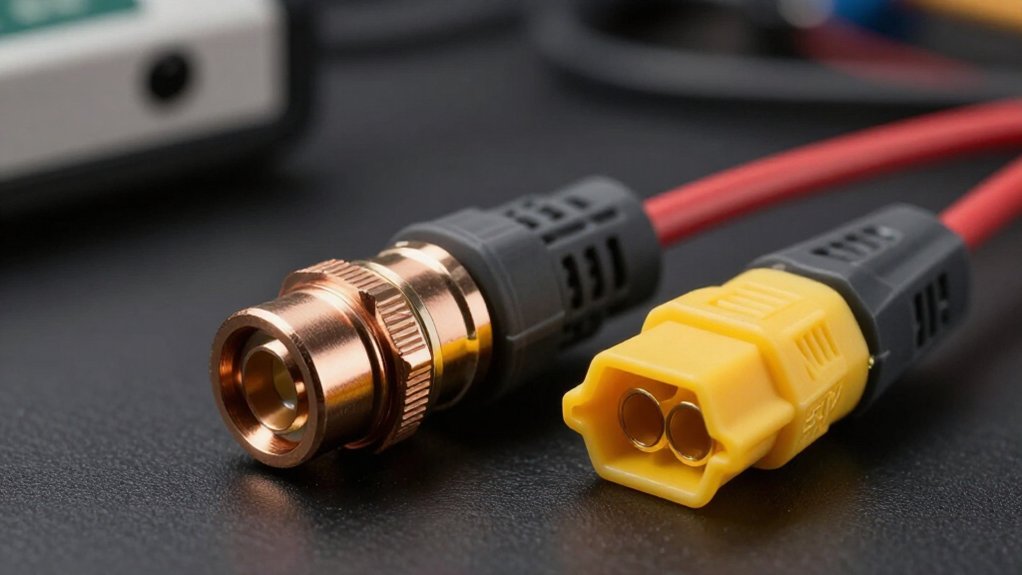
Choose EC5 when your system sustains more than 60 A: its 5 mm bullet contacts carry a typical 120 A continuous rating, versus XT60’s 60 A through 3.5 mm contacts.
At 100 A, resistance matters; each milliohm drops 0.1 V, and a 2 mΩ connection wastes 20 W as heat. Match the plug, wire gauge, battery C-rate, ESC demand, and installation space.
The details below also cover soldering, fitment, and anti-spark choices for high-current systems.
XT60 60A vs EC5 120A
XT60 connectors carry up to 60 A continuously, whereas EC5 connectors are rated for up to 120 A. You consequently get twice the stated continuous-current capacity with EC5. Choose XT60 for typical 1/10-scale RC models or standard 5-inch FPV drones when your measured load remains within its rating. Select EC5 for higher-current applications, including large 6S or 8S vehicles, where current margin matters.
| Connector | Practical selection |
|---|---|
| XT60 | Typical 1/10 RC or 5-inch FPV systems |
| EC5 | Large 6S or 8S, higher-current systems |
| Check | Verify wiring, quality, and installation |
Ratings guide selection, not guaranteed performance. You must assess peak and sustained demand, wire gauge, solder quality, and heat buildup. A poorly installed connector can limit your system before its published rating becomes fully relevant in operation.
3.5mm Vs 5mm Bullet Contacts
Contact diameter helps explain the current-rating gap: XT60 uses 3.5 mm gold-plated bullet contacts, while EC5 uses larger 5 mm contacts. The EC5’s greater contact diameter provides more conductive interface and metal cross-section, supporting its higher stated continuous rating of up to 120 A.
XT60’s 3.5 mm contacts are rated up to 60 A, making them better suited to smaller current demands. Both designs use gold plating to limit surface oxidation and maintain a low-resistance electrical connection. However, you shouldn’t treat diameter alone as a complete performance guarantee. Actual capability also depends on connector construction, contact fit, solder quality, ambient temperature, and airflow. Match your wire appropriately to the solder cups: use 14 AWG guidance for XT60 and thick 10 AWG wire for EC5.
Voltage Drop at 100A
At 100 A, resistance becomes the decisive factor: each 1 milliohm in a connector produces 0.1 V of voltage drop under (V = IR). An XT60 at this current operates well beyond its 60 A continuous rating, so its contact resistance can create significant loss and heat.
An EC5, rated to 120 A continuous, places 100 A nearer its intended capacity; nevertheless, condition and quality govern actual results. Assess the complete path:
- Clean, firmly seated contacts minimize interface resistance.
- A 2-milliohm connection drops 0.2 V and dissipates 20 W at 100 A.
- Suitable wire and sound joints prevent additional path resistance from compounding the drop.
You should measure voltage across the mated connector, because small increases in resistance convert electrical power into localized heating.
Soldering Iron Wattage Requirements
Choose a high-wattage, temperature-controlled iron so you can bring the connector cup and heavy wire to soldering temperature quickly. For XT60 assemblies, you’ll commonly solder 14 AWG wire, whereas EC5 connectors may use 10 AWG leads. Thicker wire and contact cups absorb heat faster, so inadequate iron power delays wetting and prevents solder from flowing through the joint uniformly. A small iron can leave you holding heat on the terminal too long, risking cold joints and housing damage.
Use a suitably sized tip and controlled temperature to heat both surfaces together. Feed solder after wire and cup reach working temperature. Work steadily, but don’t prolong heating; excess dwell can soften housings or misalign contacts. Fully wetted joints minimize resistance, limiting heat and conserving battery capacity.
EC5/IC5 Plug Interchangeability
A sound solder joint doesn’t guarantee connector interchangeability: EC5 and IC5 plugs use a similar 5 mm bullet-contact layout and often mate electrically, but you should verify the specific housings and contacts fit fully and securely. Treat compatibility as a mechanical and electrical check, not an assumption. Before installation, compare the battery-side and device-side connectors, then make a controlled test connection:
- Align the keyed housings without twisting or spreading either shell.
- Seat both 5 mm contacts completely; resistance or partial engagement signals a mismatch.
- Apply normal operating load and confirm the mated pair remains locked and stable.
If insertion isn’t smooth, stop rather than force the plug. Connector tolerances and quality vary, so confirm compatibility for your exact battery and device before regular use.
Gold-Plating Wear Over Time
Gold plating on XT60’s 3.5 mm and EC5’s 5 mm bullet contacts resists corrosion and preserves a low-resistance conductive interface, but repeated mating cycles gradually wear this thin surface layer. As you plug and unplug either connector, friction can expose the underlying metal. That damage raises contact resistance, increasing heat generation and voltage drop when current flows.
Inspect each connector for scratches, discoloration, corrosion, or loose bullet fit. A poor fit reduces contact pressure and can worsen localized heating. Keep the mating surfaces clean; avoid abrasive picks, sandpaper, or aggressive polishing, since they remove plating faster. Replace the connector when contacts look visibly damaged, show corrosion, or no longer mate securely. This protects your power path and helps maintain predictable performance under load conditions.
EC5 Housings Require More Space
Because EC5 connectors use 5 mm bullet contacts in a rigid housing measuring roughly 9.5 × 19.6 × 33.4 mm, they demand more installation clearance than compact XT60s. You must budget space for the body and for straight-line insertion and withdrawal movement.
- The connector can occupy scarce bay volume beside batteries, receivers, or frames.
- Its rigid profile limits routing options where leads must bend sharply.
- Service access needs finger clearance so you can grip and separate the halves.
For a high-current installation, EC5’s larger envelope may be justified, but you should model the connector’s full service path before finalizing component placement. In compact builds, XT60s can simplify wire routing and preserve usable internal volume around the battery and flight-control electronics during assembly and maintenance.
Anti-Spark Variant Availability
If you need reduced connection arcing, XT60H adds a resistor to limit sparks during mating. For higher-voltage 6S-and-above packs, you can also consider the better-documented XT90-S anti-spark design. IC5 is a Spektrum Smart connector rather than an anti-spark model.
XT60 Anti-Spark Options
Standard XT60 connectors don’t include built-in anti-spark protection, so they can arc when you connect a battery to equipment with large input capacitors. This inrush can produce a visible spark, stress contact surfaces, and create an abrupt connection event.
- Your standard XT60 relies on direct metal-to-metal engagement.
- You can consider XT90-S, which uses an internal resistor to limit arcing with high-voltage packs.
Before changing connector families, verify the exact product specification rather than relying on marketplace labels. Confirm that XT90-S physical dimensions, mating compatibility, and current rating match your wiring, battery, and load. If they don’t, instead select an appropriately rated precharge solution.
EC5 Anti-Spark Availability
EC5 connectors don’t inherently provide anti-spark behavior, so you shouldn’t treat an EC5 plug as protected against capacitor inrush without verifying its exact model and manufacturer documentation.
Unlike dedicated anti-spark designs, standard EC5 contacts mate directly, allowing the pack’s input capacitors to draw a brief, high inrush current that can produce an arc at connection. For 6S-and-above setups, choose XT90-S or QS8 when reducing connection spark is a design priority. Those variants explicitly incorporate anti-spark provisions. EC5 and IC5 may be electrically compatible, but you must confirm fit, ratings, and documented features; mating compatibility doesn’t create inrush limiting. Use the manufacturer’s datasheet to verify whether any EC5-branded product includes a separate precharge or anti-spark mechanism before directly connecting it to a high-voltage electronic system.
Racing Quad vs RC Car
For a typical 5-inch racing quad, you’ll find that an XT60 handles standard current demands with its 60 A continuous rating. In RC cars, you must account for scale and acceleration surges: XT60 suits many 1/10 models, while high-power 1/8 builds may require EC5’s 120 A capacity. Match your connector and lead gauge to the complete battery, ESC, wiring, and fitment requirements.
Racing Quad Current Demands
A typical 5-inch racing quad on a 3S or 4S LiPo commonly uses an XT60, whose 60 A continuous rating generally suits its compact power system. Your quad’s current rises sharply when you accelerate, so you should compare the ESC’s specified continuous and peak current with the complete power path. Don’t treat the XT60 rating as a system-level guarantee; resistance and heat depend on several installation details:
- Use 14 AWG wire to keep conductor resistance appropriate for an XT60-equipped build.
- Make clean, fully wetted solder joints; poor joints increase voltage loss under load.
- Inspect connector fit and provide airflow, because contact resistance and inadequate cooling can raise temperature.
This assessment helps you preserve voltage at the ESC and avoid overheating during demanding flight maneuvers consistently.
RC Car Power Surges
RC cars often impose longer high-current loads than racing quads, especially during hard acceleration, repeated throttle surges, and sustained high-speed runs. Unlike a quad’s brief punch-outs, your car can hold elevated current through consecutive launches, corner exits, and full-throttle passes. Assess the battery and ESC’s specified or measured peak current rather than relying on a connector label alone.
An XT60 is commonly rated to 60 A continuous; an EC5 is listed to 120 A, providing greater thermal margin when load duration rises. A 60 A 1/10-scale system commonly uses XT60, whereas demanding 1/8-scale and 6S–8S systems produce more sustained stress. Regardless of rating, loose contacts, weak solder joints, or undersized wire raise resistance and heat. Match wire gauge to load, secure joints, and avoid adapters between battery and ESC.
Connector Choice By Platform
Platform load profile should drive your connector choice: a standard 5-inch racing quad commonly runs an XT60, whose 60 A continuous rating suits many typical FPV power systems, while a high-current 6S or 8S 1/8-scale RC car often benefits from an EC5 rated up to 120 A continuous.
Use platform-specific current margin, not connector size alone:
- On a quad, compact XT60 hardware limits mass and handles typical flight draw.
- On a 1/10-scale car, XT60 often remains adequate when expected continuous current stays below 60 A.
- For 1/8-scale 6S/8S acceleration, EC5 adds thermal headroom; verify ESC, battery, wire gauge, quality, and peak current.
If plugs differ, install a well-made adapter or standardize your fleet. Inspect connections for heat after full-throttle test runs during demanding use.
Match Plug to Battery C-Rate
Match the connector to the battery’s expected continuous current, not merely its physical size. Calculate estimated pack current by multiplying capacity in amp-hours by C-rate. A 5,000mAh, or 5Ah, pack rated at 20C can theoretically supply 100A: 5Ah × 20C. Then compare that figure with the plug’s stated continuous rating.
XT60 connectors are commonly listed up to 60A, whereas EC5 connectors are listed up to 120A. With a 5Ah battery, 12C already equals 60A, so even a modest-capacity pack can surpass an XT60’s rating. Select EC5 when expected continuous current exceeds the XT60 limit. Don’t evaluate the plug in isolation: verify the ESC, wire gauge, battery, and manufacturer specifications. C-rate math is an estimate; use the pack’s actual continuous-discharge rating for final matching decisions.
Conclusion
Choose EC5 when your system can sustain currents near 100 to 120 A: its 5 mm contacts reduce resistance, heating, and voltage drop versus XT60’s 3.5 mm bullets. Use XT60 for compact, lower-current builds, typically up to 60 A continuous, where space and mass matter. You’ll need higher soldering power for EC5 and more enclosure clearance. Verify EC5/IC5 compatibility, consider anti-spark options, and size the connector against your battery’s C-rate and load under real peak-current conditions carefully.