Digital vs Analog RC Servo: Precision, Holding Power and Price
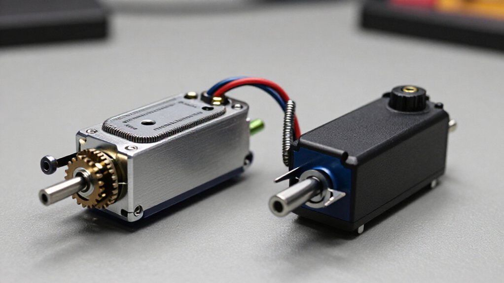
You’ll get finer centering and more aggressive active holding from a properly sized digital servo because its controller corrects errors far more often than an analog unit.
However, digital holding still can’t exceed rated torque, linkage strength, or BEC capacity, and its higher stall-current demand can cause brownouts.
Analog servos usually cost less, run quieter, and suit modest loads. Check pulse-rate compatibility, servo voltage, and wing-bay fit before buying.
Details below show their best uses.
Deadband and Signal Rates
Deadband defines the smallest input-pulse change that makes a servo move: within that ignored range, the output position remains unchanged. Narrower deadband lets you command smaller position changes and achieve finer final positioning. Digital servos typically use less deadband than analog models, so your system can resolve subtle corrections more consistently.
| Servo type | Deadband tendency |
|---|---|
| Digital | Usually narrower |
| Analog | Generally wider |
| Command effect | Digital detects smaller changes |
| Use case | Fine incremental positioning |
Receiver signals arrive near 50 Hz, which both designs accept. Analog drive commonly updates at about 50 Hz, or every 20 ms; digital drive may run near 300 to 500 Hz. If you use faster receiver updates, verify ratings. Don’t exceed 100 Hz with an unrated analog servo: it can jitter or behave erratically.
Control-Pulse Processing Differences
Both servo types accept the same basic RC PWM command, but they process and apply motor power differently. An analog servo typically interprets receiver’s command and drives its motor at about 50 Hz: one control cycle every 20 ms. Within each cycle, it applies power briefly; longer on-time increases motor drive and advances output farther.
A digital servo uses a microprocessor to interpret the same input, then issues motor-drive pulses much more often, commonly around 300-500 Hz. That higher update frequency lets electronics correct position commands sooner and regulate motion more continuously. You may see faster response, but denser switching can raise current demand and audible noise. Both designs usually accept RC PWM. Check servo/controller specifications before using refresh rates above 100 Hz, especially with analog servos.
Torque Retention Under Load
Under load, a digital servo usually holds its commanded position more firmly because it refreshes motor-drive pulses far more often, commonly 300 to 500 Hz versus about 50 Hz for an analog servo. That faster correction helps you resist aerodynamic pressure, vibration, and gravity, but it doesn’t override the servo’s rated torque or your power system’s limits. An analog unit may yield slightly or drift when its control surface or robot joint stays loaded.
Evaluate torque at the linkage: a longer output arm reduces available force, while a shorter arm increases it. Digital holding also raises current draw and heat. Size your battery, BEC, wiring, and connectors for sustained demand, and don’t let the servo remain stalled; prolonged stall conditions can overheat the motor, electronics, or both.
Programming Card Setup Time
Programming-card setup time varies by servo model, card design, and the settings you change; the analog 50 Hz and digital 300–500 Hz pulse rates describe operating behavior, not programming duration. You can’t infer setup duration from those rates, because neither specifies card menus, write cycles, confirmation steps, or available parameters. Instead, treat programming time as a product-specific workflow.
- Identify the exact servo and compatible card before you begin; unsupported combinations may not expose settings.
- Consult both manuals to determine supported options, connection order, power requirements, and required save actions.
- Change only documented parameters, then verify that the card reports or stores each selection correctly.
- Budget additional time for reading instructions and checking results.
Receiver Frame-Rate Compatibility
After configuring any servo-specific settings, match the servo to your receiver’s control-frame rate. Standard receivers send 50-Hz signals, or one command every 20 ms, and this rate generally suits analog and digital servos.
Digital models often accept 150 to 333 Hz updates, yet a 50-Hz receiver prevents you from exploiting their maximum response-rate capability. Before choosing a servo, verify your receiver’s or controller’s specified frame rate; modern equipment may provide 200- or 333-Hz output. Do not run an analog servo above 100 Hz unless its documentation explicitly approves that rate, because it may jitter or operate erratically.
If a digital servo performs poorly, reduce the rate to 50 Hz for testing: its supported update limit can vary by model. Verify compatibility in the manufacturer’s documentation first.
Gear-Train Replacement Costs
Metal-gear servos often cost more upfront, but available replacement gear sets can lower the cost of repairing a worn or damaged gear train versus replacing the entire unit. Your actual repair economics depend on model-specific parts availability, bearing design, and wear patterns.
- Verify the exact servo version before purchase; gear sets aren’t universally interchangeable.
- Compare the spare-set price with a complete servo, including your installation time.
- Inspect ball bearings: they support the output shaft under torque, reduce slop, and can extend service life.
- Account for material: metal gears offer durability but may wear faster than plastic; titanium can reduce weight and operating temperature.
Very inexpensive servos often use plastic components and brass bushings, altering long-term repair value.
Stall-Current Brownout Risk
Even a durable, repairable servo can destabilize the entire control system if its stall-current surge overwhelms the power source. A digital servo may draw only 0.12 A at 5 V in one measurement, yet consume 2.4 A when deliberately stalled. Starting or binding a servo creates a short peak that can collapse supply voltage and brown out your receiver or controller.
Size your BEC or servo supply for combined peak or stall demand, with headroom. Four high-torque servos may justify at least a 12-A supply. Test voltage while loads move or resist force; an 8-A, 5-V unit reading 5.35 V unloaded proves little. If demand can exceed capacity, isolate receiver power with a separate battery or install a higher-current BEC to maintain control integrity.
Audible Idle Noise Differences
You may hear a digital servo buzz or whirr at idle because its controller sends motor pulses hundreds of times per second to hold position. An analog servo is usually quieter because it corrects at roughly 50 Hz and may stop powering the motor when no adjustment is needed. Digital whine is often normal, although load, gear material, and pulse frequency can make it more noticeable.
Digital Servo Idle Whine
Digital servos often produce an audible idle whine because their control electronics repeatedly pulse the motor, commonly at roughly 300 to 500 Hz, to correct tiny position errors. You may hear it with no new command or external load; it usually indicates active position maintenance, not a defect. Assess it systematically:
- Listen for a steady, high-pitched tone at rest.
- Expect greater intensity when the servo resists load.
- Check that linkage binding doesn’t force continual corrections.
- Verify your supply can handle elevated current and heat.
The pulse train lets the servo detect and correct minute deviations rapidly. However, mechanical friction, poorly centered geometry, or insufficient voltage can increase correction activity and make the sound more prominent. If the tone changes abruptly, inspect mounting, gears, and control signals before assuming failure. This distinction helps you separate normal control behavior from installation-related stress and power-delivery faults during bench testing of the actuator system.
Analog Servo Quietness
Analog servos usually remain quieter at idle because their control circuits drive the motor with relatively low-rate pulses, typically near 50 Hz, and may leave it unpowered between corrections. You’ll so often hear less background sound when your model is stationary. The lower update rate reduces how often the motor receives corrective energy, so minor position errors may pass without a sustained audible tone.
Gear train construction, case resonance, supply conditions, load, and the controller’s settings all influence noise. If an external force shifts the output arm, an analog unit can still click, buzz, or hum as it corrects. Compare servos under mounting and load conditions: an analog servo may suit noise-sensitive applications, but audible behavior alone doesn’t establish accuracy, torque, or reliability.
Glider Wing Servo Selection
Size servo torque to your aileron or flap loads and linkage geometry, using oz-in or kg·cm ratings to prevent surface deflection under aerodynamic force. Confirm that the servo’s case depth and mounting pattern fit the wing’s thickness and servo bay. Choose a digital servo when you need stronger holding power and repeatable centering against load and vibration.
Torque for Control Surfaces
A glider wing servo must resist the aerodynamic hinge moment on its aileron, flap, or spoiler, not merely move a lightweight control surface. You can’t select torque from surface weight alone; load rises with airspeed, deflection, and linkage geometry.
- Read torque at your actual supply voltage, not its best-case headline value.
- Match arm length to required force: a longer servo arm reduces output force, while a shorter arm increases it.
- Choose a digital servo for surfaces that must hold position under sustained load; it generally offers stronger holding power.
- Size the BEC or receiver supply for digital-servo current, using stall-current data when available.
Common systems operate at 4.8 to 6.0 V; HV units may use 6.0 to 7.4 V. Confirm every component supports the selected voltage you choose.
Wing Thickness and Fit
Wing thickness sets a hard physical limit on servo selection, so measure the servo bay depth and the wing’s thickest section before choosing a unit. Servo categories don’t guarantee dimensional compatibility: a micro model can fit a thin glider wing where a standard car servo is too deep. Compare case height, length, mounting-tab span, and output-shaft clearance with the pocket, covering, and arm sweep.
Leave clearance for unrestricted arm travel. If your servo exceeds the wing depth, install it in an external or raised mount; don’t remove spar material. Then verify that the linkage reaches the control surface without binding through its full travel. A longer arm improves reach but reduces available force, so size the compact servo and arm geometry for aerodynamic loads.
Digital Holding Power
Digital servos can hold a glider’s ailerons or flaps nearer their commanded position under aerodynamic load because their control electronics correct position errors more aggressively than typical analog units. You should size the installation from estimated hinge load, not the digital label alone. Evaluate:
- Compare rated torque, in oz-in or kg-cm, with expected surface load.
- Account for arm length: a longer arm reduces linkage force.
- Verify receiver supply or BEC current capacity; digital correction increases demand.
- Match rated voltage to your system: standard units often use 4.8–6.0 V, while high-voltage models typically need 6.0–7.4 V.
Then confirm speed, case dimensions, and mounting fit. A suitably rated analog servo may outperform an undersized digital model, whereas a specified digital unit provides resistance to load-induced displacement.
Match Servo Voltage to BEC
Before you power the system, compare each servo’s rated voltage with the BEC output and set the supply within that range. Standard servos commonly accept 4.8 to 6.0 V, whereas high-voltage units may require 6.0 to 7.4 V. Don’t assume a fixed ESC BEC suits every installation; configure an adjustable BEC correctly or use an external BEC or 2S LiPo for a compatible high-voltage servo.
If the ESC BEC powers your receiver, confirm the receiver also tolerates the selected voltage. Check continuous-current capacity, not voltage alone. Digital servos can demand substantial current, especially near stall, so size the supply from total stall-current specifications and retain headroom. Finally, measure voltage under representative load. Sag can disrupt control, and nominal ratings can mislead: a 5 V supply measured 5.35 V in testing.
Conclusion
When you choose between analog and digital RC servos, match control precision, torque retention, pulse-rate compatibility, and current demand to your aircraft. You’ll gain tighter centering and stronger holding from digital units, but you must budget for higher price, idle noise, and stall-current brownout risk. Analog servos remain efficient, quiet, and economical where loads stay moderate. Verify receiver frame rate, program only when needed, select glider wing servos, and match servo voltage to your BEC.