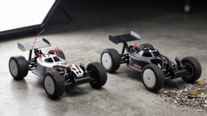
How to Choose an ESC for a Brushless Motor: Amps, Cells and Sensors
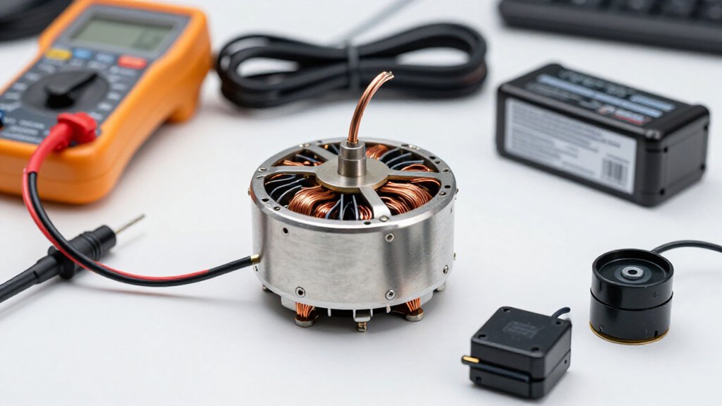
Choose an ESC whose continuous current rating meets or exceeds your motor’s draw, and you’ll add roughly 10 to 20% headroom for limited cooling or demanding loads.
Verify whether a rating applies per motor or across all channels. Match the ESC’s voltage range to your battery’s cell count and fully charged voltage.
Confirm sensor support and firmware match your motor’s Hall or encoder feedback. Check brake, reverse, wiring, cooling, and warranty details before purchase; tests show more.
Amps, Cells, and Sensors
Start with current capacity: choose an ESC rated for at least the motor’s expected continuous draw—a 60 A motor needs a 60 A ESC or higher—and use burst ratings only to assess brief peaks, not as a substitute for continuous capacity.
Match the ESC’s voltage range to your battery; a 3S LiPo is 11.1 V nominal, so confirm the controller supports it. Set low-voltage cutoff for the chemistry: LiPo packs typically need about 3.0–3.4 V per cell, while NiMH cells can discharge to about 0.8 V per cell. Then choose sensing to suit control needs. A sensored ESC reads Hall-sensor feedback for smoother, precise low-speed operation; a sensorless ESC relies on back-EMF and offers simpler operation when that behavior suits your application. Verify these specifications together before purchase.
Measure Motor Current Draw
Check the motor manufacturer’s specifications for expected current at your battery voltage and intended propeller or load. Treat that figure as a starting point, because actual draw can change with voltage and operating conditions. For a reliable measurement, test with the battery and load you’ll use in operation, then compare the result with the ESC’s continuous current rating. If the motor draws 60 A, select an ESC rated for at least 60 A continuous per motor; an additional 10 to 20% headroom gives you margin without pushing extra current into the motor.
Check burst and continuous ratings separately, since a short-duration burst figure doesn’t replace the continuous rating. With a 4-in-1 ESC, compare each motor’s draw against its per-motor rating, not only the board’s aggregate rating.
Thermal Headroom and Cooling
Because ESC current ratings depend on test conditions, heatsinking, and airflow, choose continuous capacity 10 to 20% above the motor’s expected draw, adding more margin when cooling is limited. Treat burst ratings as brief limits, usually under 10 seconds; they can’t replace adequate continuous capacity. Give the ESC clear airflow, and use a heat sink to move heat away. A thermally controlled fan can increase cooling under load. Keep vents, heat sinks, and fans free of dust or blockage, and remain within rated voltage and current limits to reduce thermal-shutdown risk.
| Condition | Response |
|---|---|
| Limited airflow | Add margin |
| Under-load heat | Fan assists |
| Burst rating | <10 seconds |
Check temperatures during representative operation; if the ESC approaches its thermal limit, improve airflow or select a higher-capacity unit before sustained use.
Sensor Types and Compatibility
A sensorless ESC estimates rotor position from back EMF after the motor starts spinning, while a sensored ESC uses feedback such as Hall signals for reliable low-speed operation. Match the ESC’s sensor support, Hall connections, and control mode to your motor’s feedback hardware. Because sensorless startup depends on sufficient back EMF, check that the ESC can start the motor reliably under your expected load.
Sensored vs. Sensorless
Sensored ESCs use rotor-position feedback, typically from Hall Effect sensors, to synchronize phase output and deliver smooth acceleration at low RPM. Because the controller receives rotor angle directly, you get predictable commutation before the motor builds speed. That feedback improves launch smoothness and low-speed control, where sensorless timing can be less stable.
A sensorless ESC instead estimates rotor position from back EMF, which becomes usable only after rotation begins. It starts the motor with a predetermined sequence; startup may feel less smooth at low speed. This simpler approach is common in UAVs and suits higher-speed applications. If you need reliable low-speed startup and precise control, choose a sensored system that supports your motor’s feedback interface. Otherwise, sensorless control can reduce system complexity in your application.
Motor Sensor Compatibility
After choosing sensored or sensorless control, verify that the ESC supports your motor’s specific sensor type and interface.
Hall-effect sensors provide rotor-position feedback, synchronizing phase output for reliable startup and smooth acceleration. Feedback also enables precise low-RPM control, where back-EMF estimation may be less effective. Confirm that the ESC accepts your motor’s sensor signal and interface; sensored systems aren’t universally interchangeable.
For encoder feedback, identify the standard. Sin/Cos encoders support smooth vector control; SSI or BiSS encoders suit high-resolution applications. Check the ESC’s supported signal formats and resolution. Also verify firmware and settings: some ESCs support multiple sensor types through software configuration. A mismatch may prevent correct commutation or disable feedback control. Match the required wiring before purchase, and confirm low-speed feedback operation directly.
Hall Sensor Connections
When your motor uses Hall sensors, verify that the ESC supports Hall feedback and matches the motor’s sensor interface before connecting them. Hall-effect devices report rotor position, letting the ESC synchronize phase switching with rotor angle. This feedback supports smoother acceleration and more precise control at low RPM. Check ESC documentation for supported Hall input and confirm the motor’s sensor interface is compatible; a matching connector alone doesn’t prove compatibility.
Sensorless ESCs don’t use Hall connections; they estimate rotor position from back EMF. Choose Hall feedback when your application needs reliable low-speed operation and precise control. Keep the Hall signal connection distinct from the motor’s phase leads, and follow the ESC’s specified interface. This distinction matters when selecting a controller.
Confirm the controller supports the sensor type your motor provides before final selection.
Sensorless Startup Considerations
Because a sensorless ESC can’t detect rotor position from back-EMF at standstill, it starts the motor with a predetermined switching sequence and uses back-EMF feedback once the rotor turns fast enough. At low speed, back-EMF is weak or unavailable, so startup may feel less smooth when you apply a heavy load. A sensored ESC reads rotor position from Hall-effect sensors, helping you achieve more reliable low-speed startup and acceleration.
Check sensor compatibility before choosing: a sensored motor needs an ESC that supports its sensor type and a matching connection. A sensorless setup instead depends on the ESC’s back-EMF detection, with no rotor-position signal at standstill. Sensorless motors are common in UAVs, but don’t assume every motor and ESC combination will start equally well. If your application demands reliable low-speed operation or loaded starts, verify the pairing under those conditions; sensor feedback may be the better fit, especially where startup consistency affects control and flight safety.
Brake and Reverse Modes
Check that your ESC’s firmware supports the brake and reverse modes your application requires, and verify compatibility with your motor. In an RC car, calibrate throttle and brake as the manufacturer directs, then compare adjustable brake settings to match your driving style. Configure reverse as specified and test all settings safely before normal use.
Brake Mode Types
Brake and reverse modes control two distinct responses to throttle input: brake mode uses the ESC to resist motor rotation when you reduce the throttle, while reverse mode drives the motor in the opposite direction. These functions aren’t interchangeable: braking decelerates the vehicle, whereas reverse changes the direction of motor rotation.
Depending on your ESC’s firmware, reverse may engage after you return the throttle to neutral; braking remains a response to throttle reduction. Because manufacturers implement these behaviors differently, consult your ESC’s instructions before setup rather than assuming identical operation across models. Calibrate your transmitter’s throttle range, then test both responses with the wheels clear of the ground. This check confirms that the ESC interprets your commands correctly without allowing the vehicle to move.
Reverse Mode Settings
Once you understand how braking and reverse differ, check that your ESC supports the reverse behavior you need.
In an RC car, braking slows the motor while reverse drives it in the opposite direction. Because brake and reverse settings vary by ESC and firmware, compare programmable options before choosing. Confirm that you can tune braking strength and reverse behavior for your application, rather than assuming every controller uses the same sequence or response.
Follow the manufacturer’s instructions to assign throttle and brake functions, then calibrate the ESC’s throttle range. Proper calibration helps prevent erratic response when you apply either function. After installation, test braking and reverse safely in a controlled area. If either response feels inconsistent, review the settings and recalibrate before continued use.
Motor Compatibility
Because brake and reverse behavior depends on ESC firmware and configuration, confirm that the controller supports the modes your motor and vehicle require.
For an RC car, check whether reverse is enabled and whether the ESC requires braking before it engages reverse. This distinction affects how you control deceleration and direction changes; it also determines whether reverse is available immediately or only after a brake command.
Match brake strength to the motor and vehicle. Stronger braking can raise current demand and heat, so choose settings that remain within the ESC’s ratings. A setting that’s too aggressive may impose excessive electrical and thermal load without improving useful control.
If you need precise low-speed response, consider a sensored ESC. Its rotor-position feedback can support smoother operation, helping you modulate braking and reverse more accurately. Confirm that the ESC’s firmware and mode match the motor’s sensor system and intended vehicle application.
Setup And Safety
Before enabling brake or reverse, confirm that the ESC supports the mode and that it’s compatible with your motor setup; then follow the manufacturer’s instructions to configure the settings and calibrate the throttle and brake ranges.
Before changing settings or connecting the battery, verify polarity and secure every motor and ESC connection to reduce short-circuit risk. Because procedures vary by ESC, use its manual for mode selection and calibration; incorrect ranges can cause erratic response. Remove the propeller, apply low power, and test brake and reverse while keeping clear of moving parts.
Observe response and temperature. If braking or reversing causes overheating or unreliable operation, stop testing. Check the motor and ESC ratings, wiring, and configuration, then let the ESC cool before further operation. Don’t assume reverse works identically across controllers; confirm any required throttle sequence or separate enable setting before restoring normal power.
Connector and Wiring Match
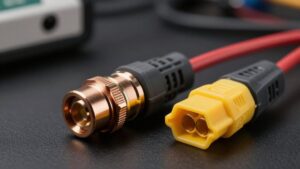
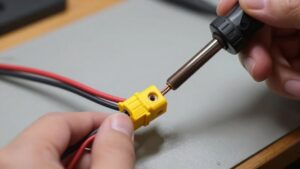
Match each ESC connection to the correct wire and pinout before applying power. Connect the battery’s positive and negative leads to matching ESC terminals; reversing polarity can damage components. Verify labels and connector orientation carefully. Join the motor’s three phase wires to ESC outputs with compatible bullet connectors or secure solder joints. Swap any two phase wires to reverse rotation, or select the direction in ESC settings.
Connect the ESC’s receiver or signal lead to the receiver’s throttle input. When you pair different brands, check the connector pinout; matching plug shapes don’t guarantee matching signal, power, and ground positions. Insulate exposed solder joints with heat-shrink tubing to reduce short-circuit risk. Before energizing the system, inspect each connection for polarity, seating, and insulation.
Warranty and Support
When comparing ESCs, review the warranty terms for coverage of manufacturing defects and performance issues. You should read exclusions and claim procedures before buying, since coverage may depend on installation and operating conditions.
Choose a seller or manufacturer that responds promptly to technical questions. Useful support can help you isolate battery faults, overheating, and connectivity problems without replacing compatible components unnecessarily.
Read detailed reviews for reliability patterns, compatibility issues, and how the company handled failures. Give greater weight to feedback from users running a similar motor, battery, and vehicle setup; their experience better reflects your electrical load and installation.
Also research the brand’s reputation and community resources. Brushless-combo comparison threads may provide practical guidance after purchase, especially when you’re diagnosing setup problems in practice.
Fake Amperage Claims
Beyond warranty terms and support, verify that an ESC’s amperage rating reflects its actual current-handling limit, not how fast it’ll make the motor run.
Check four details before you trust a headline figure:
- Identify whether the rating is continuous or burst; burst current lasts only briefly, often seconds, and exceeds the continuous limit.
- For a 4-in-1 ESC, confirm whether amps apply per motor or across all channels; 60 A per motor can mean 240 A total.
- Compare the rating with expected motor draw and voltage, allowing roughly 10 to 20% current headroom where appropriate.
- Treat unusually high claims cautiously: test conditions, heatsinking, and airflow affect ratings. Verify specifications and assess cooling and real-load performance, not the label alone, under your intended conditions and load in practice.
Battery Cell Count
Battery Cell Count
Check that the ESC supports your battery’s cell count and fully charged voltage before connecting it. Nominal voltage alone isn’t sufficient: charging raises a LiPo’s voltage, and the ESC must tolerate that maximum.
- A typical 3S LiPo supplies 11.1 V nominally but reaches 12.6 V when fully charged; choose an ESC rated for at least 12.6 V.
- Match the ESC’s stated cell range to your pack; a 3S to 8S model supports 11.1 to 33.6 V.
- Don’t assume every controller accepts the same pack: some handle up to 6S, while others stop at 4S or lower.
- Verify both limits in the specifications before connection; exceeding either the cell-count or voltage rating can damage your ESC. Treat the lower limit as decisive when ratings appear inconsistent; confirm with manufacturer.
Conclusion
Choose an ESC by matching its verified current rating to your motor’s measured draw, then leave thermal headroom for sustained use. Confirm the ESC supports your battery’s cell count and the motor’s sensor type. Check brake and reverse modes, connector polarity, and wire gauge before installation.
Don’t trust headline amp claims without reliable specifications. Adequate cooling and compatible wiring protect performance; warranty terms and responsive support matter if problems arise. Choose for real operating conditions.