How to Change RC Battery Connectors Without Damaging Your Pack
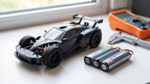
To change an RC battery connector, match the plug type, current rating, and polarity to your battery and ESC. Disconnect the pack, cover nearby electronics, and secure it on a nonconductive surface.
Work on one lead at a time, insulating each freed wire before exposing the other.
Use a temperature-controlled iron, and don’t overheat the connector. Verify polarity with a multimeter before reconnecting.
The steps below explain how to inspect joints and spot problems before flight.
Battery Pack Compatibility Check
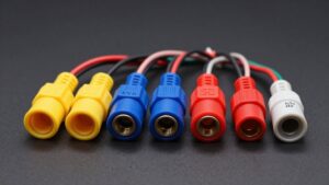
Before ordering a replacement connector or adapter, check the battery, ESC, and charger plugs; common types include XT60, XT90, Deans/T-plug, Tamiya, EC, and IC. You should confirm that each plug and adapter can handle your setup’s current demand; high-current operation places greater stress on contacts. Before connecting anything, verify positive and negative terminals match the battery and ESC polarity. Connector shapes don’t guarantee identical polarity layouts, so inspect markings and documentation first.
If the plugs differ, an adapter can provide compatibility without permanently modifying the battery. However, each added connection may increase resistance, so check that the complete path remains appropriate. For a long-term setup, using the same suitable connector on the battery and vehicle can simplify compatibility and reduce connection points.
Connector and Wire Selection
Once you’ve confirmed compatibility, choose a connector and wire that fit your ESC, charging equipment, current requirements, and available space.
- Check plugs fitted to the ESC and charger before ordering; matching prevents adapter issues.
- XT60 and XT90 connectors are common choices, but neither suits every model.
- Match connector and wire ratings to your system’s current demand; higher-current setups need components rated accordingly.
- Confirm the connector and wire fit the available space without forcing bends or strain.
A compatible adapter lets you connect different plug types without permanently altering the pack, though each added connection can increase resistance. A direct match reduces connection points and unnecessary added resistance. Don’t lengthen battery or ESC leads unnecessarily; on powerful setups, follow the manufacturer’s wiring requirements to limit electrical risk.
Step 1: Cover Nearby Electronics
Remove the battery from the RC model before changing its connector to keep nearby electronics from being powered or accidentally shorted.
Keep the battery and exposed leads clear of the ESC, receiver, charger, and other conductive parts on your workbench. Work on one battery wire at a time; insulate its exposed end fully before you expose the other wire. This sequence limits the chance of a short that could damage nearby electronics.
While soldering, keep loose strands and bare conductors separated from each other and from nearby components. Don’t let a lead rest against a circuit board or metal tool. Before reconnecting the battery to your model, inspect each joint for stray strands or bridges, then verify polarity against the model’s wiring or connector markings. Reversed polarity can damage the ESC and other electronics, so don’t reconnect until the orientation is confirmed before applying power.
Step 2: Secure the Battery Pack
Disconnect the battery from the model and charger, then place it on a clear, stable work surface away from combustible materials. Keep tools and loose hardware clear of battery terminals.
Keep the pack stationary in a connector holder or with firm, nonconductive support so it can’t shift under hand pressure. Arrange it so both battery wires remain visible, with exposed positive and negative conductors kept apart. Work on one wire at a time, and fully insulate the first conductor before you expose the second.
Never cut both battery wires at once; a tool can bridge them and short the pack. Stop if you find swelling, leakage, unusual heat, or visible damage to the pack or wiring. Don’t continue; have the battery assessed before further use.
Step 3: Desolder the Existing Connector
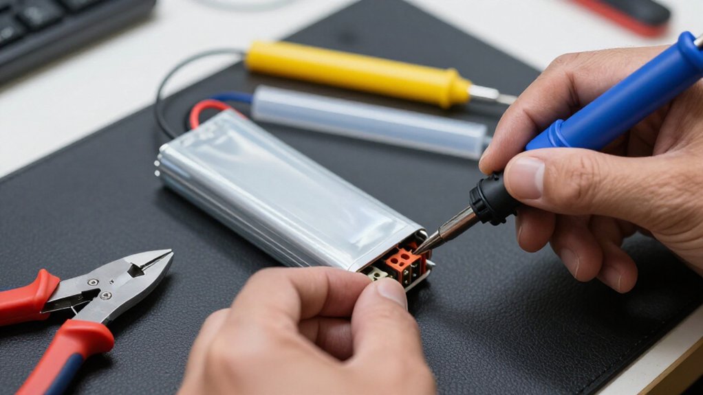
With the battery disconnected from the model and charger, secure the old connector in a holder so it can’t shift. Desolder only one battery lead at a time, keeping the other lead fully insulated; never expose both conductors together, because they could short. Use a temperature-controlled iron with enough power for the wire and connector. Heat the solder joint only long enough to free the wire.
Don’t let the connector housing melt or distort from excess heat. Avoid pulling hard; let the joint release the wire cleanly. Once the lead is free, cover its exposed end with heat-shrink before you work on the other lead. Let the connector and terminals cool completely, then inspect the wires and insulation for damage before fitting a replacement.
Step 4: Tin the New Connector Contacts
Before heating the contacts, confirm the connector’s positive and negative markings, since polarity layouts vary. Clean each contact and use electrical solder with a suitable iron that heats the terminal promptly. Apply solder to the contact until it forms a thin, even coating.
If you’re tinning a cup-style terminal, don’t fill the cup; excess solder can obstruct wire insertion and create an unreliable joint. Keep molten solder confined to its contact so it can’t bridge adjacent terminals. Avoid plumbing solder and corrosive acid-based flux because they can damage electrical connections. Once each contact has an even coating, set the connector on a heat-safe surface and let it cool fully before handling it or fitting it into its housing. Inspect the contacts for stray solder.
Step 5: Control Iron Temperature
Choose a temperature-controlled soldering iron with enough power for the wire gauge and connector; 60 W or more is a common choice. Set the iron to match your solder and connector, following their manufacturers’ guidance instead of using one temperature for every job. Let the iron reach its set temperature. Keep the tip clean so it transfers heat efficiently to the wire and terminal.
Heat the joint briefly but thoroughly. An underpowered iron may tempt you to hold it against the connector longer; prolonged contact can melt the housing and damage nearby insulation. Use an adequately powered tool to complete the joint promptly while maintaining control. If your connector requires it, let soldered terminals cool fully before you fit them into the housing.
Step 6: Trim Excess Solder Carefully
Once the solder joint has cooled naturally, use small, sharp cutters to remove loose solder or stray wire strands, keeping the blades clear of the battery leads. Don’t move the joint while solder remains molten; disturbance can weaken the connection. Trim one conductor at a time, keeping positive and negative leads separated to prevent a short.
Cut only loose material. Keep the blades away from wire strands and the connector terminal; cutting either can weaken the joint and increase resistance. Leave enough solder for a smooth, secure bond.
Don’t scrape or reheat the joint unnecessarily, as either action can disturb the connection. Work slowly, stopping once loose material is removed. Check each cut before proceeding, and don’t pull or twist the leads while trimming.
Verify Polarity With a Multimeter
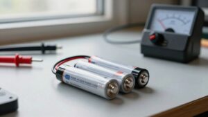
With the solder joint trimmed and cool, verify polarity using a multimeter before connecting the pack. Set your meter to DC volts and choose a range above the pack’s expected voltage. Touch the red probe to the connector’s suspected positive contact and the black probe to its suspected negative contact. A positive reading confirms your probe orientation; a minus sign means you’ve reversed the probes, so swap them and recheck.
Don’t trust red and black wire colours alone. Confirm the connector’s terminal orientation, then verify polarity again after fitting the replacement. Keep probe tips from bridging the contacts; a short can damage the battery or start a fire. If the reading’s unexpected or you can’t measure securely, stop and ask an experienced RC technician.
Diagnosing Intermittent Power Loss
If your RC model cuts out under acceleration or vibration but works again after you reconnect the battery, inspect the battery and ESC plugs and their solder joints for an intermittent connection.
Disconnect the battery before handling anything. Gently move each wire at its solder joint, then check contacts, housing, strands, polarity, compatibility, and full seating. Stop using a plug that gets excessively hot or remains intermittent; ask an experienced RC technician to assess damaged wiring or uncertain joints.
| Sign | Possible fault |
|---|---|
| Cutout under load | Loose plug or joint |
| Heat or discoloration | High resistance |
| Exposed strands | Damaged wire |
| Poor fit | Incompatible or unseated connector |
Cracks or weak bonding can also interrupt current. Don’t pull on live wiring; verify polarity against the pack and ESC before reconnecting, and seat the plug firmly each time.
Inspect Joints After Flights
After each flight, let the battery and connector cool, then inspect them for unusual heat, discoloration, melted plastic, or a burnt smell.
Inspect each solder joint for cracks, movement, loose wire strands, or conductor exposed where heat-shrink should insulate it. Gently pull each wire to confirm it’s firmly attached; don’t twist or stress the connector.
Check that the connector fits snugly and its contacts stay clean. A loose fit or heat can point to a damaged contact or weak solder joint.
If you find a loose or damaged joint, or excessive heat, stop using the pack. Don’t fly it again until someone experienced repairs the connection and verifies its insulation and security. Use good lighting, and don’t bridge terminals with metal tools.
Conclusion
Before you power up, confirm the connector matches your pack’s current rating, wire gauge, and polarity. Keep nearby electronics protected, and secure the battery so it can’t shift while you work. Use controlled heat, trim solder carefully, and verify voltage with a multimeter before reconnecting equipment. After flights, inspect joints for movement, discoloration, or cracking. If power cuts out intermittently, stop flying and repair the fault before the next launch. Never risk a damaged pack.