How to Convert a Brushed RC Car to Brushless for More Speed
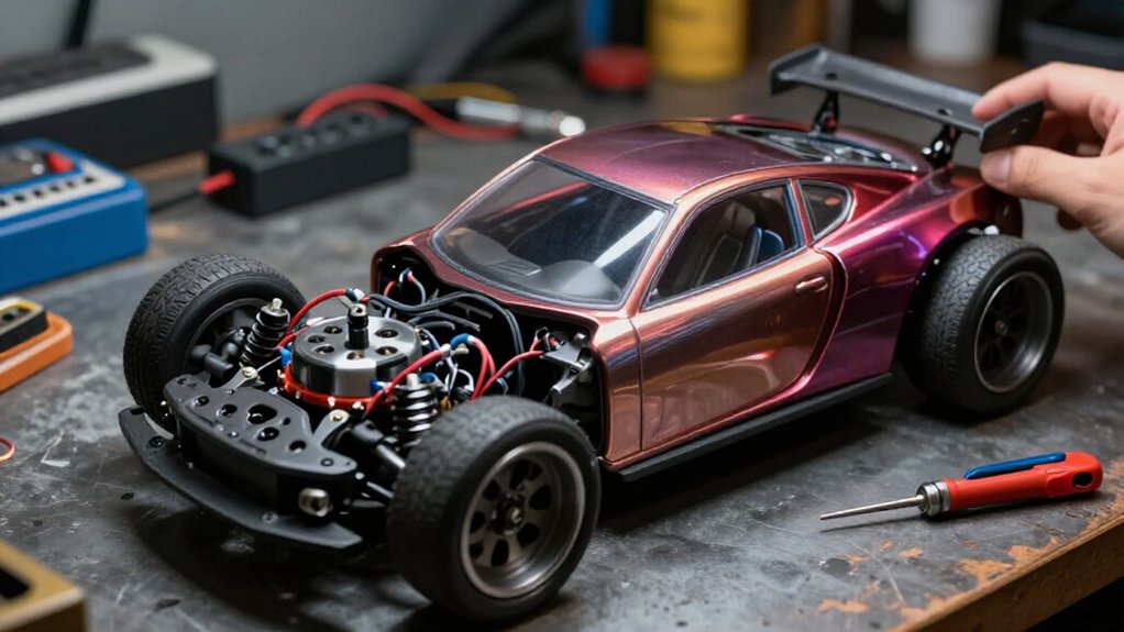
To convert your brushed RC car to brushless, match the motor and ESC to the chassis, battery voltage, and current needs. Disconnect the battery, remove the shell, and inspect gears for wear before fitting the motor. Set slight pinion-to-spur backlash, secure compatible metal-to-metal screws with blue thread-lock, then calibrate the ESC using its manual.
Test gradually, measure motor temperature, and stop to cool or reduce gearing if it overheats. Check receiver connections; more checks help keep speed reliably and safely.
Brushless Speed Gains
A brushless conversion can increase speed and efficiency, but the gain depends on the motor’s kV rating, battery voltage, gearing, and vehicle setup. Motor kV estimates unloaded revolutions per minute per volt. For example, a 3,000 kV motor on a 2-cell LiPo at 7.4 V nominal spins at about 22,200 RPM without a load. That figure isn’t a road-speed prediction: drivetrain losses, tire diameter, traction, and aerodynamic drag affect what you measure.
Raising voltage or selecting higher kV increases RPM, while taller gearing can raise top speed; shorter gearing trades speed for cooler, safer operation. To judge the upgrade, record speed before and after under similar conditions, using the same surface, tires, and measurement method consistently.
Motor, ESC, and Battery Compatibility
To turn brushless speed gains into a reliable setup, match the motor and ESC to your battery’s voltage and current demands.
- Match your motor and ESC cell limits: 2S LiPo supplies 7.4 V nominal; 3S supplies 11.1 V. Never exceed either rating.
- Choose an ESC with current capacity above the motor’s specified maximum; too little headroom can cause overheating or shutdown.
- Pair sensorless motors with sensorless ESCs; sensored systems need compatible wiring and connectors.
- Check physical fit, shaft diameter, pinion-to-spur mesh, and battery discharge capability. A 5000 mAh, 30C pack can nominally deliver 150 A, if connectors and ESC support it.
Calculate pack current as capacity in amp-hours multiplied by its C rating, then confirm the entire power path can safely carry that load.
Step 1: Remove the Car Body Shell
Before accessing the electronics, switch off the car and disconnect its battery. Locate each body clip, usually a small R-shaped or hairpin retainer, that secures the shell to a body post. Pull each clip carefully and set it aside so you won’t lose it. Check each post for a remaining retainer, and keep all clips together; you’ll need them to refit the shell securely after the conversion.
With all clips removed, grip the shell evenly and lift it straight up from the posts. If it catches or resists, stop and check for a missed clip or body mount still attached rather than forcing it free. Place the shell and clips on a clean, stable surface away from tools to prevent scratches or damage while you work on the car.
Step 2: Disconnect the Battery Pack
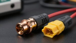
With the shell removed, switch off the RC car before disconnecting its battery pack. Verify that the car’s electronics are off. Locate the battery connector and separate its plug halves by gripping the plug bodies, not the wires. Pulling on the leads can damage the insulation or loosen a connection.
If the connector has a retaining tab, press it while you pull the plug halves apart; don’t force a locked connector. Once unplugged, keep the battery leads separated from each other and from metal parts. Contact between conductors can cause a short circuit, so don’t let loose leads rest against hardware or tools. Place the disconnected battery on a nonconductive surface while you continue the conversion.
Step 3: Remove the Brushed Motor Mounts
Check whether the brushed motor mount can securely hold the brushless motor; some mounts work with an adapter, so remove yours only if it doesn’t fit. Before loosening it, note the mount’s position and gear mesh so you can reproduce those settings later. Photographing the assembly can help you record spacer placement and screw locations.
Use the correct driver to unscrew the mount from the chassis; don’t force stuck fasteners or strip their heads. Keep screws and spacers together in a labeled container, since the replacement may need them. Check that the replacement mount’s bolt pattern matches your motor and that its position will permit pinion-to-spur alignment. Before drilling or cutting, test-fit the mount and confirm clearance around the chassis, gears, and nearby components.
Step 4: Fit Brushless Motor/Esc
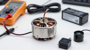
Choose a brushless motor that matches the car’s chassis and drivetrain, including its size, shaft diameter, mounting pattern, and pinion gear. Match the ESC to the motor’s sensored or sensorless design and verify its voltage and current ratings support your battery and motor. Confirm the ESC accepts your battery’s cell count and connector, and that its receiver lead fits your receiver for throttle control.
Securely mount the motor and set gear mesh with slight backlash. Align the pinion and spur gears before you power the system.
Connect the motor and ESC as specified in their manuals. Calibrate the ESC according to its instructions. Raise the wheels and apply low throttle to check motor direction and smooth operation.
Step 5: Set ESC Throttle Endpoints
Before setting throttle endpoints, disconnect the motor or lift the car securely, then switch on the transmitter and set throttle trim and sub-trim to neutral. Consult the ESC’s manual for its calibration sequence; many units require you to hold the setup button while powering on. When prompted, move the trigger fully to throttle, then fully to brake or reverse, and release it to neutral. This teaches the ESC all three signal endpoints.
Watch the status light or listen for beeps to confirm calibration, because indicators and sequences vary by manufacturer and model. If the ESC rejects an endpoint, check that your transmitter’s throttle channel uses the correct direction, then repeat the procedure. Keep the trigger at each limit until the ESC registers it; don’t assume calibration succeeded just because setup mode ended. Recheck neutral response before reconnecting the motor or placing the car on the ground before driving.
Step 6: Apply Thread-Lock to Screws
Because brushless motors produce vibration that can loosen fasteners, apply a small drop of medium-strength blue thread-lock to the threads of metal-to-metal motor-mount screws and compatible drivetrain screws. Keep it off plastic parts, since some formulas can damage them. Apply it only to screw threads; don’t let it enter the motor or bearings, and don’t coat the entire screw.
Seat each fastener, then tighten it securely while maintaining the motor’s alignment and correct gear mesh. Follow the thread-lock label for curing time before you run the car. Choose blue, removable thread-lock for small RC hardware. Avoid red permanent-strength products: removing those screws may require heat, which can damage nearby components. Check that no excess compound reaches gears or moving parts during assembly and service.
Monitor Motor Temperature
After a short run, check the motor temperature with an infrared thermometer, then repeat the check after each longer run. Measure the motor can promptly after stopping; don’t touch it, because a hot can can burn your skin. Keep the temperature below about 160 to 180°F (71 to 82°C). If it approaches or exceeds that range, stop driving and let the motor cool fully before another run.
If the motor overheats, reduce gearing or throttle load before you drive again. Record each reading with your gearing, battery, and run time. These notes can help you identify setups that repeatedly produce excessive heat, so you can make a targeted change rather than guessing. Check temperature under comparable conditions when you evaluate adjustments. Ambient conditions and run duration can affect readings.
ESC Calibration Errors
If the ESC won’t calibrate, first confirm it’s set for your motor type: a brushless ESC generally can’t calibrate a brushed motor, and vice versa. Turn on your transmitter, center throttle trim and sub-trim, set endpoints to 100%, and disable throttle mixing and reversing. Use the ESC’s exact sequence: hold full throttle at power-up, then record neutral and full brake/reverse when prompted.
| Symptom | Check | Fix |
|---|---|---|
| Wrong range | Throttle direction | Reverse channel; recalibrate |
| No response | Receiver lead | Check orientation |
If calibration still fails, verify battery voltage and receiver signal-lead orientation, then consult the manual for startup tones and its procedure. If the ESC reads the throttle range backward, reverse the transmitter’s throttle channel and recalibrate; don’t swap phase wires to correct a signal issue.
Inspect Drivetrain Gear Wear
Inspect the pinion, spur, and differential gears for chipped or missing teeth; a brushless motor’s higher torque can strip them quickly. Check faces for rounded edges, deep grooves, or uneven wear. Worn teeth can skip under load and produce clicking or grinding sounds, so replace them before testing.
Rotate the drivetrain and check pinion-to-spur mesh: you should feel slight backlash, with a small amount of movement and no binding. A tight mesh overheats and wears gears; excessive looseness encourages tooth skipping. Inspect plastic gears for cracks, and confirm the pinion and spur don’t wobble or shift on their shafts. Replace damaged or loose parts before installing or running the higher-power setup. Brush grit and debris from the teeth; abrasive particles accelerate wear and can ruin serviceable gears.
Conclusion
Converting your brushed RC car to brushless can deliver a speed gain, but only when you match the motor, ESC, and battery to the drivetrain. Before testing, secure mounts with thread-lock, calibrate the ESC, and check gearing for wear. Monitor motor temperature during short runs; excess heat signals an unsuitable setup or gearing. Reinspect fasteners and drivetrain parts after each session. With careful compatibility checks and maintenance, you’ll gain speed without sacrificing reliability or control.