How to Power LED Lights on an RC Car From the Receiver or Battery
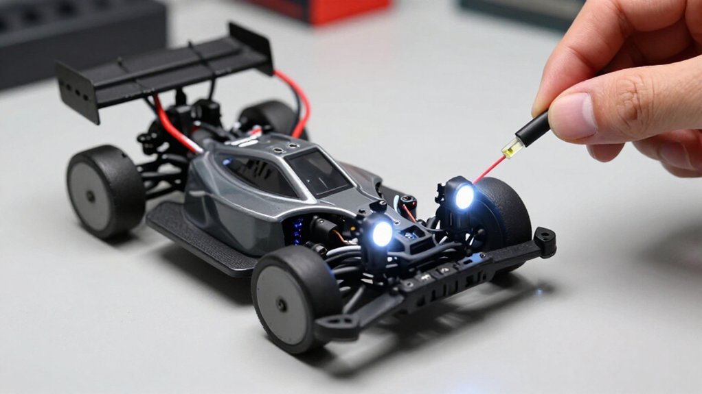
You can power low-current LEDs from your receiver’s 5 V BEC if their voltage and current requirements fit its capacity; keep the BEC’s load limits in mind.
For 12 V strips or higher-current lights, use a suitably rated battery, not a spare receiver channel. Check polarity, match the source voltage to the lights, and disconnect the RC battery before wiring.
Secure and insulate connections, then test safely. Steps below explain installation, troubleshooting, and lead repairs.
Receiver vs. Battery Power
You can power a few LEDs from the receiver’s shared supply, which comes from the ESC’s BEC or a receiver battery and is about 5 VDC in this example. A receiver’s pins share this supply; they don’t provide independent power. With suitable resistors, you can run a few LEDs. Many need 2–3 volts, so you can wire two in series across the 5 V supply.
Don’t connect a 12 V LED strip to the receiver; its 5 V supply won’t light it. A strip may draw around 400 mA, so don’t rely on receiver power. Instead, power strips directly from a suitably rated battery, such as the main pack or a separate 3S (12 V) Li-Po. This keeps the ESC’s BEC available for servos.
Check Voltage and Polarity
Before connecting the lights, check that their rated voltage matches the power source: the receiver’s roughly 5 V supply won’t power a 12 V strip, which needs a suitably rated battery. Check the specifications for each component, and don’t assume the receiver can deliver a strip’s required voltage.
For individual LEDs, account for their typical 2–3 V rating; use appropriate resistors and wiring when connecting them to a higher-voltage source. Across a 5 V supply, you can wire two LEDs in series, then connect multiple pairs in parallel.
- Confirm your battery meets the strip’s rated voltage.
- Match positive and negative leads at every connection.
- Check wiring before applying power to avoid faults.
Reversed connections can prevent operation or damage components. Inspect for exposed conductors.
Step 1: Elevate the Chassis Securely
With the car switched off, place it on a stable stand that supports the chassis and lifts all four wheels clear of the work surface. Position the stand under a flat chassis area, not beneath the body shell, arms, shocks, or other suspension components. They can shift and destabilize the car.
Before you reach toward the wiring, check that the chassis sits and can’t wobble, slide, or tip. Adjust the support points until the stand holds the car securely. Keep the car switched off while you position and verify the stand; don’t energize controls during setup. Choose a stand arrangement that leaves the receiver and battery accessible for the lighting installation, without forcing you to move the elevated car or strain its wiring.
Step 2: Disconnect the RC Battery
Once the chassis is stable, disconnect the RC battery before opening the receiver compartment or handling any LED wiring.
Keep the battery unplugged while you connect the LEDs to a free receiver channel or route their wires. This prevents an energized circuit from causing a short. Don’t rely on the vehicle’s switch alone; it may not isolate receiver power. Check connectors for a secure fit and confirm that no cable can reach wheels, gears, or other moving parts. Before restoring power, inspect the wiring for pinching, exposed conductors, or damage.
When the checks are complete, reconnect the battery and switch on the vehicle to test the lights. Observe operation, then switch off and disconnect the battery again before making any wiring adjustments or repairs.
Step 3: Install a Y-harness
Plug one end of the Y-harness into a free receiver channel, then connect the LED kit and its compatible device to the two branches. A Y-harness duplicates the channel’s signal and power paths; it doesn’t create an independent supply or give your transmitter separate LED on/off control. Before powering the car, verify the LED kit’s voltage and current requirements, then assess the receiver’s BEC rating and the combined load.
A typical receiver supply provides about 5 V, while a full LED strip may draw roughly 400 mA. That load can exceed what the BEC can safely support, especially when servos need current. Keep receiver power for modest LED loads only, where safe. Don’t expect a 12 V strip to run from the receiver’s roughly 5 V supply; use a suitable battery instead.
Step 4: Connect the LED Lead to the Y-Harness
Before connecting the LED lead, match its positive and negative wires to the receiver connector’s polarity; reversing them can keep the lights from working.
Plug the LED lead into one branch of the Y-harness, then connect the harness to a receiver channel. The LEDs then share the channel’s signal and power. The harness doesn’t create additional power capacity: its receiver pins draw from one supply, the ESC’s BEC or a receiver battery. Check that the LEDs’ voltage and current requirements fall within the receiver system’s limits. A 5 V receiver supply won’t operate a 12 V strip. If your lights need more current than the receiver can provide, power them from a suitable battery and use a receiver-controlled switch. Don’t route their load through the Y-harness.
Step 5: Aim Lights for Visibility
Aim each LED in its light bucket toward the area you want to illuminate. Set the headlights forward and slightly downward so they light the driving surface instead of sending useful output into the sky.
Then test the lights in a dark area. Observe the car and its path, and adjust each angle until both remain clearly visible. Once you’re satisfied with the beam pattern, secure each LED inside its bucket using the mounting screws or a small dab of glue. This helps prevent vibration from shifting the aim during operation. After positioning the lights, route their wires and tape them down, keeping every lead clear of wheels, gears, steering linkages, and other moving parts. Check clearance across the full steering range before driving.
Step 6: Insulate Exposed Connector Contacts
Insulate exposed connector contacts to prevent accidental short circuits. Before you connect LED leads to the receiver or battery, cover every unused pin and bare wire end near those connections with electrical tape or heat-shrink tubing. Choose insulation suited to the wire and connector, and apply it so it fully covers conductive metal without placing material across the mating surfaces.
Keep the plug’s contact area clear; otherwise, insulation can prevent secure seating, increase resistance, or interrupt power. After you connect the LED wiring, inspect each receiver and battery connection closely. Confirm that no metal contacts remain exposed and that unused pins and wire ends stay covered. If tape shifts or tubing leaves a gap, reposition or replace the insulation before operating the car safely.
Test the Headlights in Darkness
With the contacts insulated, test the headlights in a dark area, where you can judge their brightness and aim clearly. Connect the battery and switch on the RC car; LED kits should illuminate with the vehicle. Check that every headlight LED sits securely in its light bucket and stays lit. Confirm the beam points correctly without exposing wiring to moving parts.
If a lamp appears dim or stays dark, switch off the car before inspecting its connectors and power source. Make sure the supply matches the light kit: a 12-volt LED strip won’t run from the receiver’s approximately 5-volt output. Secure loose leads and keep them clear of steering and drivetrain components. Then switch the vehicle off and verify the headlights turn off with it.
LED Flicker Under Load
If the LEDs flicker when the servos move, the receiver’s BEC may be overloaded. A full strip can draw about 400 mA, adding load the BEC may not comfortably supply. Receiver pins share one power bus, so a free channel isn’t an independent source or switch.
| Check | What it means |
|---|---|
| Servo movement | BEC load changes |
| Strip on receiver | Adds LED current |
| Flickering lights | Supply may sag |
| Safer feed | Main or separate battery |
Keep the BEC available for the receiver and servos. If flicker occurs when servos or other loads operate, move the lights to a suitable battery source. Match the source to the strip’s voltage rating and use connections; disconnect power before changing the wiring. This reduces receiver-supply demand without treating an unused channel as extra capacity.
Replace Damaged LED Leads
Once the power supply is stable, replace any damaged LED leads with wire of suitable gauge, matching the LED’s polarity before reconnecting it. Use wire that can carry the LED current, then make a firm, secure splice or connector joint and insulate it fully to prevent shorts.
If the LED has a resistor, keep it in series with the replacement lead; it limits current and protects the LED. Before reconnecting, verify polarity against the LED’s markings or the original wiring. Reversed leads can prevent illumination.
Route repaired wiring along the bodywork, secure it with tape, and keep it clear of wheels, gears, steering links, and other moving parts. Check connector security and insulation over exposed conductors. Power on the vehicle and test the lights.
Conclusion
Choose receiver power when your LEDs match the receiver’s voltage and current limits; use the battery only with a correctly rated regulator. Before wiring, secure the chassis, disconnect the RC battery, verify polarity, and add a Y-harness without forcing connectors. Insulate every exposed contact. Reconnect power only after checking your work, then test the headlights in darkness.
If your LEDs flicker under load, don’t ignore it; reduce demand or isolate the supply. Replace damaged leads.