How to Solder an XT60 Connector for a Clean, Strong Joint
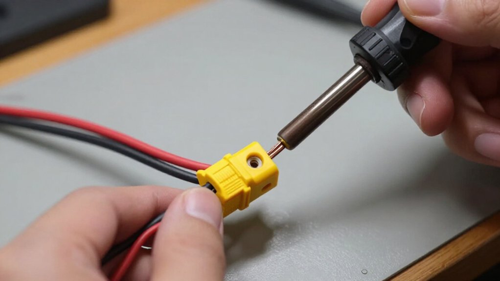
Disconnect battery, separate exposed poles, and verify polarity with a multimeter before soldering.
Clamp XT60 gently, keeping its contact cup accessible. Set iron near 365°C for leaded solder or 380°C for lead-free, using clean, tinned chisel tip.
Pre-tin the cup and 12 AWG strands, then reflow the cup and insert wire fully.
Keep heat brief, hold the joint still as it cools, add heat-shrink, and inspect. Check connector temperature after flight; further guidance can help prevent failures.
Preventing XT60 Housing Melt
To limit heat transfer to the XT60 housing, start around 365°C (±10°C) with leaded solder or 380°C (±15°C) with lead-free solder; these are starting points, not fixed connector specifications.
Use a clean, pre-tinned chisel or hoof-style tip to heat the wire and contact together. This helps the joint reach temperature quickly while limiting heat transfer to the housing. If solder doesn’t flow within a couple of seconds, improve tip contact and preparation rather than raising the temperature.
Avoid repeated reheating. If solder beads on the tip or the iron loses heat, stop, clean and re-tin the tip, then let the connector cool before continuing. After soldering, inspect the housing for warping, softening, discoloration, or cracks. If its shape has changed, replace the connector before use.
Soldering Iron Temperature and Wattage
Once you’ve prepared the joint to limit heat reaching the housing, set your iron to about 365°C (±10°C) for leaded solder or 380°C (±15°C) for lead-free solder. These are practical starting points, not fixed XT60 specifications. Your iron’s working temperature differs from the solder’s melting range; choose a setting that lets solder flow promptly when the tip contacts both parts. Choose sufficient wattage for steady heat recovery.
- Use a clean, pre-tinned chisel or hoof-style tip; its broad contact heats wire and terminal quickly.
- If solder won’t flow within a couple of seconds, improve tip contact and preparation instead of raising temperature.
- If heat drops or solder beads, stop; clean and re-tin the tip.
- Let the connector cool, then improve heat delivery before you resume.
Step 1: Clamp the XT60 Securely
Before soldering, secure the fully disconnected XT60 in a stable holder so it can’t shift as you heat the contact. Position the connector so the contact cup remains accessible. Leave enough clearance for the iron tip and wire to meet the cup without the tool touching the housing.
Clamp the nylon body gently; don’t squeeze it hard. Excessive pressure can deform the housing or disturb the brass contact, compromising alignment. If you use the mating XT60 half to help hold the connector straight, do so only on a fully disconnected harness. Keep exposed positive and negative contacts apart to prevent an accidental short.
Before you begin soldering, check that the contact sits straight and stays secure. If clamping makes it move or flexes the housing, stop and adjust your setup. Don’t proceed until the connector is stable.
Step 2: Pre-Tin the XT60 Contacts
With the XT60 secured, clean and pre-tin the iron tip, then lightly coat the empty contact cup with solder; don’t fill it. Use a temperature-controlled iron set to about 365°C (±10°C) for leaded solder or 380°C (±15°C) for lead-free solder. Treat these values as starting points, not fixed rules; your iron, tip, and working conditions may require adjustment.
Hold the tinned tip against the cup’s inner wall and feed solder into the heated area. Let it wet the metal in a thin, even layer; don’t pool solder or touch the plastic housing. If solder doesn’t flow within a couple of seconds, stop. Improve tip contact or preparation rather than repeatedly reheating the contact. Let the joint cool, then confirm the cup remains open and clean inside.
Step 3: Tin the 12 AWG Wire
Strip enough insulation for the 12 AWG conductor to reach the bottom of the XT60 contact cup, then gather the strands so none can spread toward the opposite pole. Secure the wire so it can’t move, and work over a heat-resistant surface with good ventilation. Use a clean, pre-tinned chisel or hoof-style iron tip to transfer heat evenly.
Touch its face to the strands, then feed solder into the heated wire, not onto the iron. Apply enough solder for it to wick through the conductor and coat the strands. Stop when the bundle looks uniformly covered; don’t leave a large blob. Keep the iron clear of nearby plastic, and avoid touching its hot tip. Let the tinned wire cool completely on a heat-resistant surface.
Step 4: Seat Wire in Contact Cup
Reheat the pre-tinned contact cup until its solder re-flows, then insert the tinned 12 AWG wire fully to the bottom in one pass. Keep the connector stable in a heat-resistant holder, and work in a ventilated area while wearing eye protection.
The insulation should stop short enough to let the conductor reach the cup’s bottom. The cup needs only a light solder coating; don’t add more than it can hold. Apply the iron to the contact so the existing solder melts uniformly. Push the wire straight down until it bottoms out, completing insertion in that single heating pass. Keep the lead motionless as the joint cools, then check that it remains seated and no loose strand or solder bridge is present.
Step 5: Keep Excess Solder Off the Rim
Keep solder below the XT60 contact cup’s rim so the opening stays clear. Pre-tin the cup with only a light layer; excess solder can spill onto the edge and obstruct the contact. Use a clean, pre-tinned chisel- or hoof-style tip to heat the cup and wire efficiently. This helps solder flow into the joint instead of collecting at the rim.
Verify the stripped conductor reaches the cup’s bottom, then seat it fully as the solder re-flows. Add only enough solder to wet the conductor and cup; don’t fill the opening. Before the joint cools, confirm the contact opening remains clear. After cooling, inspect for a smooth, wetted fillet, a solder bridge, or stray strands near the opposite pole. Correct any defect before connecting power.
Step 6: Apply Heat Shrink
Slide appropriately sized heat-shrink tubing onto the wire before soldering, since you can’t add it after attaching the connector. Once the joint has cooled, inspect the soldering and confirm the tubing will cover exposed conductor and the solder joint without obstructing the XT60 housing. Center the tubing over the joint and leave no bare wire that could contact the opposite pole or another conductive surface.
Use a heat gun to shrink the tubing evenly. Keep the heat moving; concentrated heat can soften or deform the connector’s polyamide housing. After cooling, check that the tubing is snug and intact, with no strands or bare metal exposed. Aim heat at the tubing, not the connector, and follow the tubing maker’s temperature guidance whenever available for safety.
Verify Polarity With Multimeter
Before soldering, disconnect the battery and separate the wire ends, then set your multimeter to DC volts. Use the polarity marks molded into the XT60’s housing to identify its positive and negative contacts. Touch the red probe to the marked positive contact and the black probe to the marked negative contact. A positive voltage reading confirms the polarity.
If the display shows a negative value, the probes are reversed relative to the contacts; switch them and confirm the reading. If it reads near zero, check that the probes make contact and that the meter is set to DC volts. Verify polarity before soldering so you can correct a wiring error. After soldering, recheck the harness while disconnected before connecting it to a battery.
Mating Connector Heat Protection
With polarity confirmed, you can plug the mating XT60 into the disconnected harness to hold the housing and contacts aligned while soldering. Treat this half strictly as an alignment aid, never as electrical isolation. Disconnect the battery completely before you start or resume work.
Keep exposed positive and negative contacts apart from each other and every conductive surface; a short can cause burns, fire, or damage. Use a clean, pre-tinned tip to heat wire and contact together. Make one controlled joint; repeated reheating can carry damaging heat into the plastic housing.
| Condition | Your action | Why it matters |
|---|---|---|
| Battery | disconnected | prevents energizing |
| Contacts | separated | avoids shorting |
| Mating half | seated | steadies alignment |
| Tip | clean, pre-tinned | transfers heat efficiently |
| Brief heating | protects housing | preserves fit |
Proceed calmly.
Check Post-Flight Connector Temperature
After a flight, check the XT60 housing and nearby wire for unusual warmth, ideally with an infrared thermometer so you don’t touch hot or exposed contacts. Let the connector cool before inspecting it, and keep the battery disconnected while you assess the joint.
Compare both connector halves and each pole under similar conditions; a single noticeably hotter contact may point to a loose, resistive, or poorly soldered joint. If heat persists or rises rapidly, stop using the connector until you’ve inspected the solder joint and contact fit.
Replace it if heat has warped or softened the housing, shifted a contact, damaged insulation, or left the mating connection insecure. Don’t resume operation until the replacement mates firmly and the wiring remains undamaged on the bench.
Conclusion
After your next flight, disconnect the battery and check the XT60 housing and wires for unusual warmth. A hot connector can signal excess resistance from a weak solder joint, damaged contact, or poor fit. Let everything cool before inspection, and don’t touch exposed conductors. Recheck polarity with a multimeter before reconnecting, and replace any melted or discolored connector. A clean, secure joint should stay cool under normal load; correct faults before flying again.